The MGA With An Attitude
| MGAguru.com |
|
MGAguru.com |
MGA Guru Is GOING MOBILE - (August 16 - August 31, 2024)
Friday August 16, 2024:
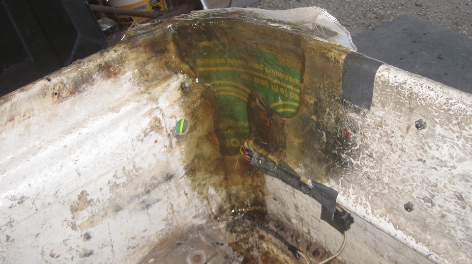
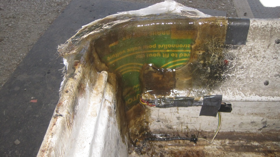
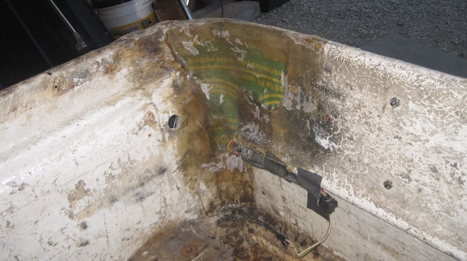
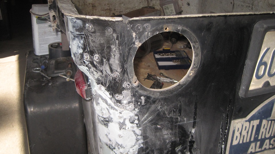
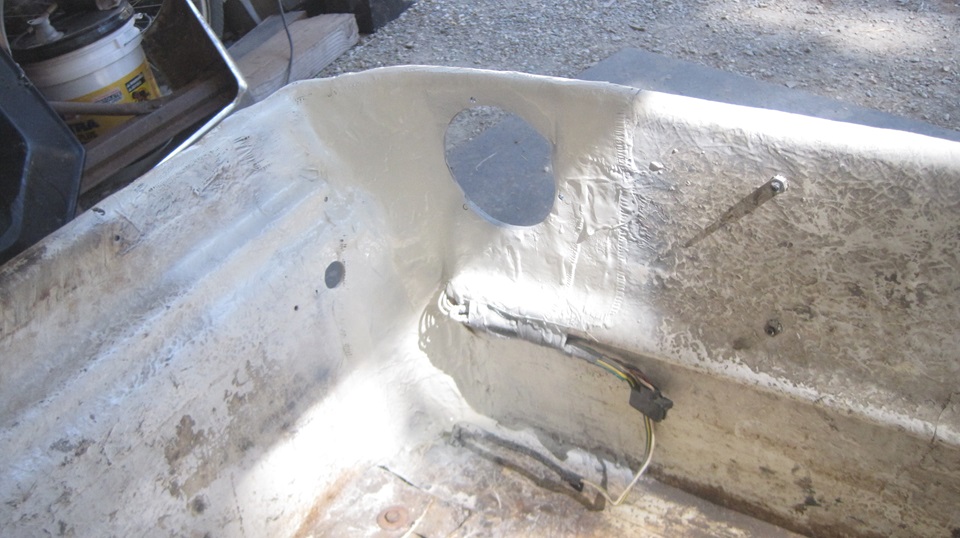
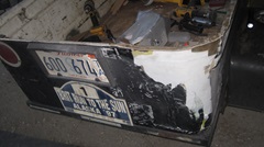
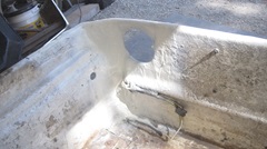
Today we took a few shifts at 2-hour intervals to lay up several layers of fiberglass cloth and resin to build up thickness of the box wall in the RR corner, as well as building up the top flange around the corner. This went well, and by evening it was set up and hard enough to bust your fist if you punched it. Then remove the tubing, trim the top flange to appropriate width, and sand it smooth inside.


Drop the cover on it for a test fit. Tomorrow we get to sand off the paper , do come finishing work, re-fit the tail light re-attach the cover hing, and maybe pain tit inside and out, if we get that far.
Saturday August 17, 2024:
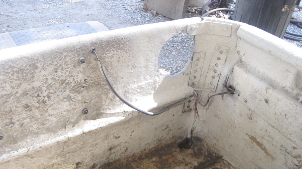
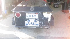
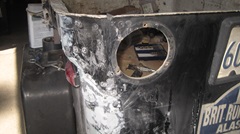
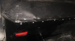
Remove left tail light for finishing work. Re-cut hole for right tail light mounting. A little sanding and finishing around the edges.
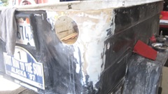
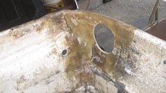
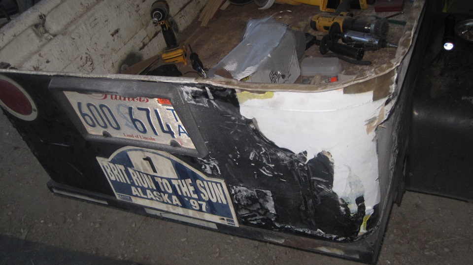
Sand off the paper on the outside. Two or three passes with Bondo on the outside, mostly the right side to fill a few cracks and joints. Sand it all flat a few times. Spray some aerosol paint, gloss black outside and gloss white inside. Will let it dry overnight. Will install tail lights and cover tomorrow.

Sunday August 18, 2024:
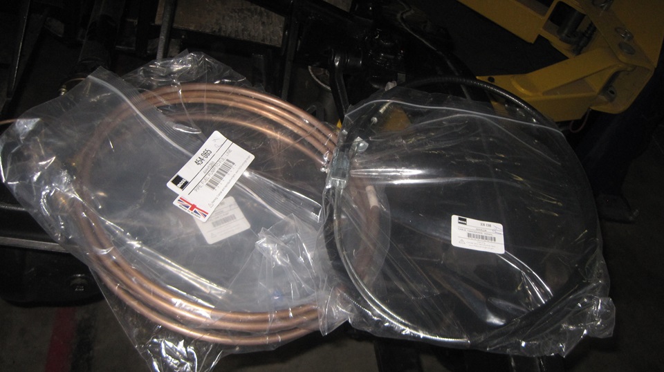
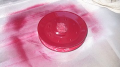
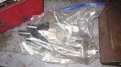
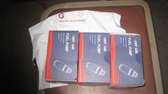
Time to jump into the parts package that arrived Friday. We got rubber parts to install the fuel tank, and fuel pipes, and a hand brake cable. Lots of little parts like brake pipe banjo bolts to finish hydraulics on the rolling chassis. And a bunch of little parts to restock inventory in the Magic Trailer. And hey, we got a new (straight) crank shaft pulley for our car, so it hopefully will stop chewing up fan belts. Get that piece painted right away.
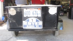
 Got the tail lights and RR marker light reinstalled, wired up and working. Ran into a lot of missing or broken screws for reattaching the cover hinge, and had to knock off around sun down. Then there was a power failure at 9-pm killing the rest of the night, check back in the morning.
Monday August 19, 2024
Still no power this morning, so we headed down to Angels Camp for breakfast (and WiFi). Called Moss to report a few missing parts and part number errors to get a few more small parts on the way. About noonish, a quick fuel stop, then head to the local lumber yard, hardware store to pick up lots of #10 screws (mostly short). Twelve miles up the hill back to the shop. After stopping a minute for a traffic light in Murphys, the engine took to running on three cylinders for the last three miles. So some of that was 2nd gear hills instead of 3rd gear, but we made it okay. Pulling spark plug wires, discover no fire on #2 cylinder. Suspect the points closing up again. Will check into that later. Seemed like a good time to take the rest of the day off.
Tuesday August 20, 2024
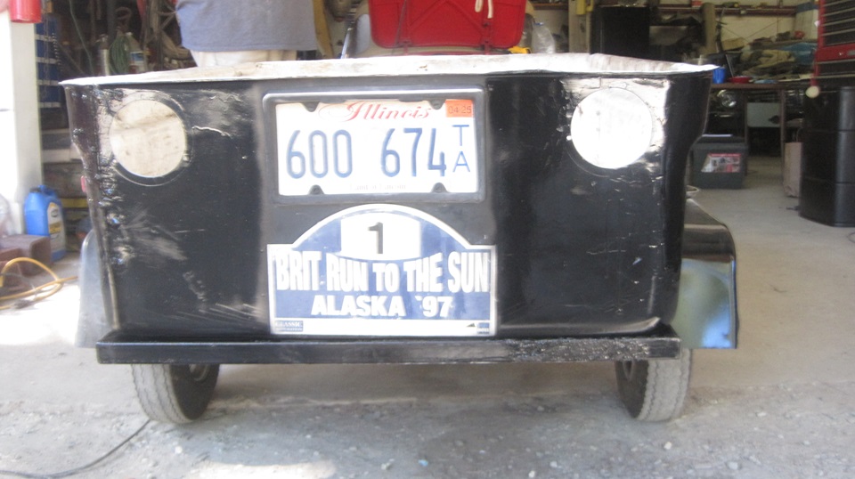
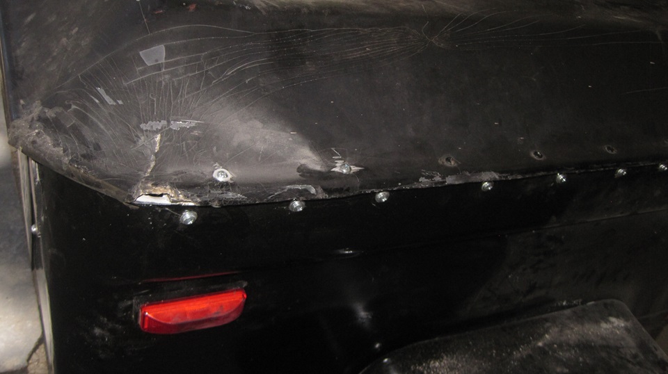
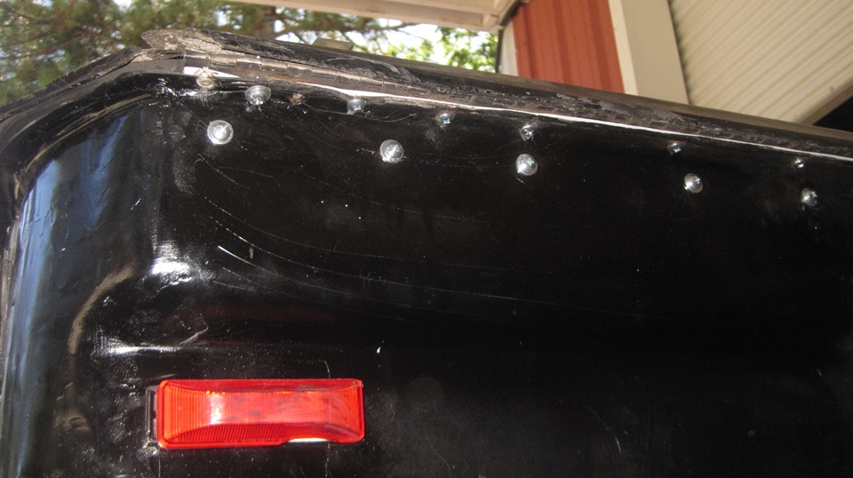
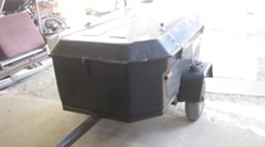
Lots of new #10 screws and nuts and washers in hand, so we jump in like we might know what we/re doing. Start drilling holes out to 7/32' clearance size to install new #10 screws. Use screws of minimal length to leave the least length inside. Use flat washers to shim screws shorter sometimes, to avoid cutting them to length after installation. Use flat washers under screw heads where possible to strain relieve the fiberglass cover on the outside. About 40 screws in all, so it took a while, but, finished, and the cover fits and latches properly. Just need to insert a bit of foam rubber weather strip inside the piano hinge later.


I did spritz a little gloss white paint on the inside of the hinge, and a little gloss black paint around the outside edges to hide the shiny new screws, and it was time to be packing things away.


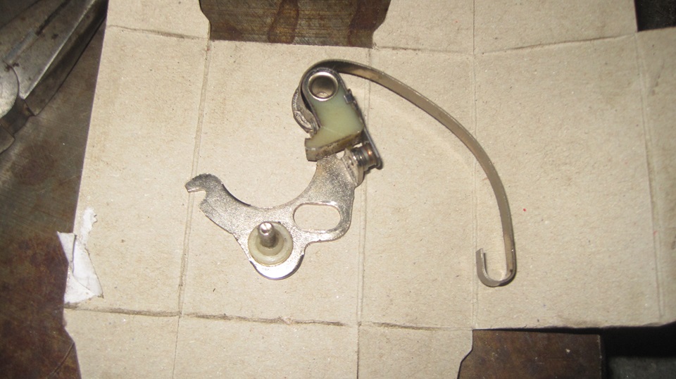
Not going anywhere until I check out the no-fire on #2 issue. Pull out the distributor to verify it is time
 to install new points, again. This time get rid of the red plastic and white plastic points that wear down the rubbing foot in a few hundred miles. And bring out the second distributor to change points in that one as well. And while we're at it, this must be the right opportunity to install the new bronze bushing in that one with the new vacuum unit but badly worn bushing. While I was disassembling the distributor in preparation for changing the bushing, Elliot was digging into the tote boxes to retrieve the new bushing, which he had just squirreled away there a few days ago. But now we can't find the new bushing? Wow, problems never cease. Knock off for dinner, and see if things might look better in the morning. -- But we did change points in the distributor in the car to get it running on all four cylinders again, at least ready for a breakfast run. Thus time we installed the "premium Aftermarket Points" from Moss motors ($23.95 please). At least these have aPhenolic rubbing foot, so we'll see.
Wednesday August 21, 2024
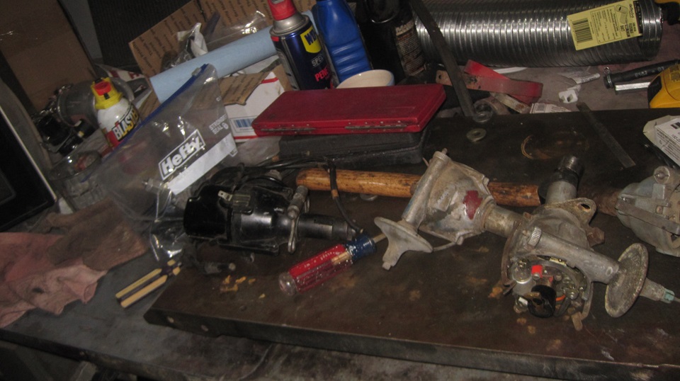
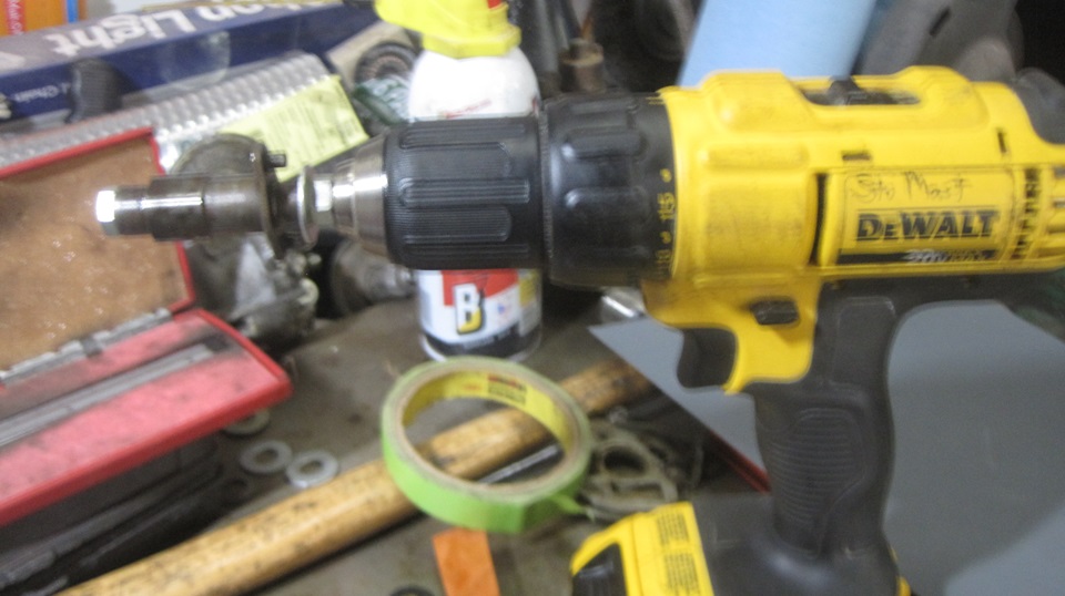
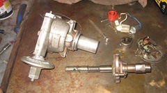
This was destined to be Distributor Tech Day. there were several used distributors lying around, so since we could not find the new bronze bushing, we decided to sort through the used distributors to find one with the least worn bushing, and build that into a good rebuilt spare distributor,possibly using some parts from the worn out one we had just disassembled. Yeah, I can see a sea of loose parts spreading out on the bench along with lots of tools. The badly worn one just disassembled had a "flat cam",meaning the cam was worn badly on the apexes of the cam lobes, so don't use that piece. The "found" distributor with the very good bushing had a slightly rusty cam surface needing polishing. This led to a quick trip down the hill to The Red Store in Murphys to pick up some 600-grit emery paper (and another gallon of lacquer thinner). We found a 5/16 inch bolt long enough to pass through the center of the rotor cam so it could be chucked up in the electric drill for spinning. With emery paper and oil and a little patience we buffed off the rust and polished up the cam quite nicely.


Getting better at knocking out the cross pin for the bottom end drive dog and getting the distributors reassembled in correct configuration. Picking the best parts from different assemblies, looking at DM2 and DM2.P2 and 25D distributors with different kinds of weights and links and springs, not so easy to get a proper match of working parts. The more I learn, the more I know what I don't know, and what special tools I don't have. Pretty sure it would be easier to send one off to the Distributor Doctor to have it rebuilt professionally. But in the end we had the one in the car fixed up okay, and a nice spare distributor with a tight bushing and mostly new tune-up parts. Both of those have working vacuum units, and we now have another nearly new spare vacuum unit that had recently been installed in the daily use worn out distributor, which was now mostly scrap parts. Heck of a tech day. I recon we both picked up some new life experience skills.


Friday August 23, 2024
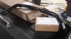 Good morning, we have a package delivery. It is a new ADDCO front sway bar for Stu's restomod rolling chassis, something to do sometime soon. An hour later another package, another sway bar for Stu's daily driver MGA. I forgot we had ordered two at the same time. Now Stu is out of town for a week, so we may have to ask the help where his car is parked.
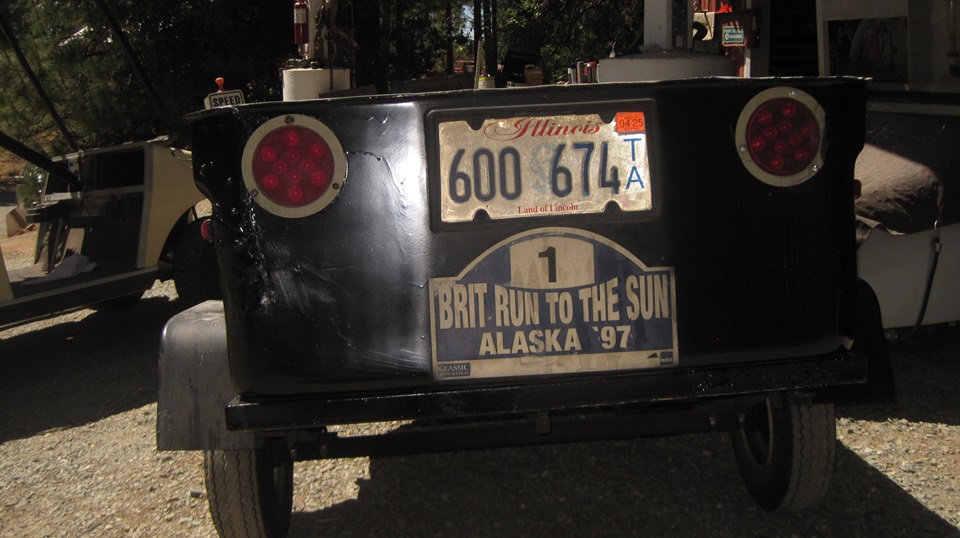
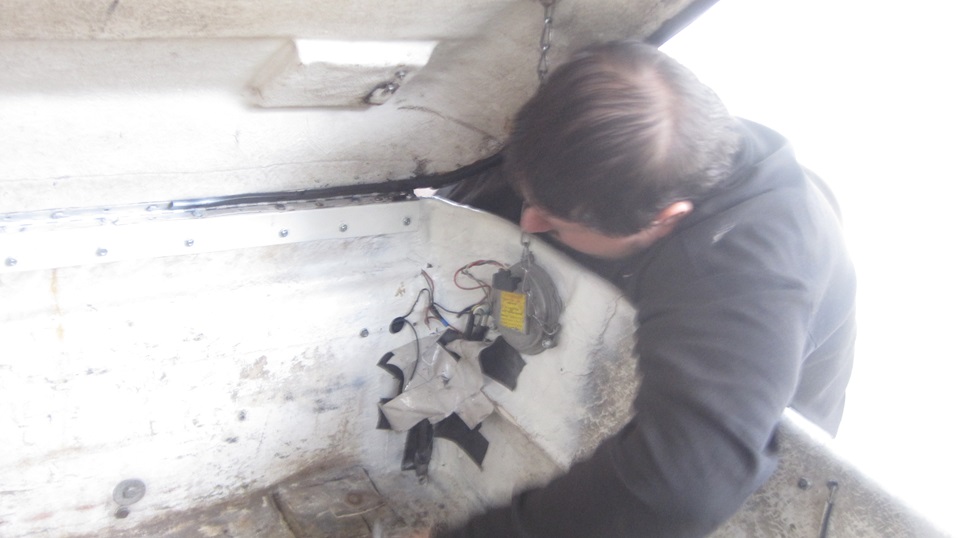
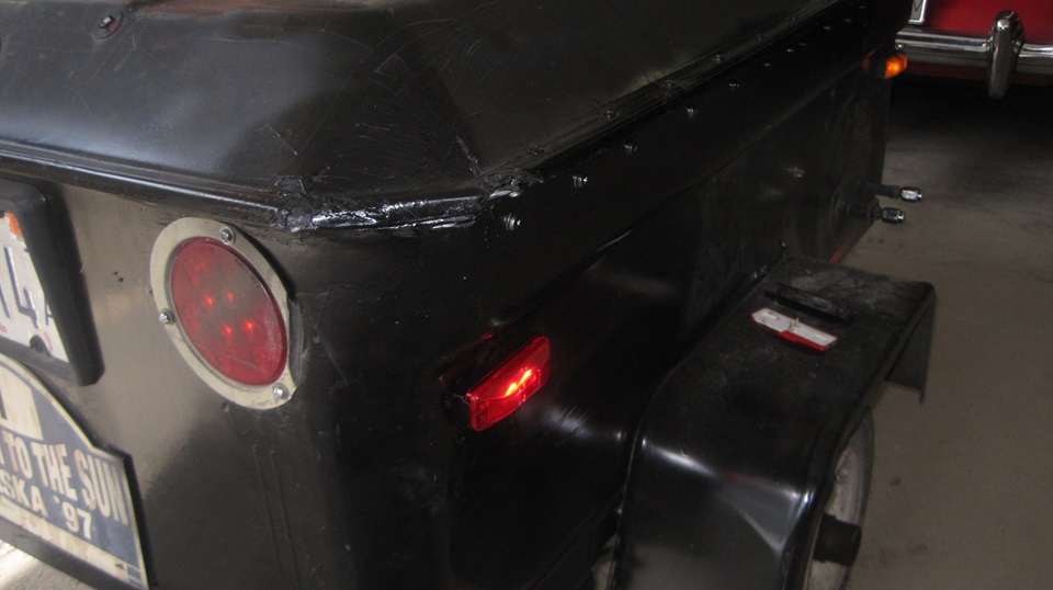
-- Meanwhile Elliot got busy installing the new side marker light on the trailer. I recon he has seen this often enough, so I was relegated to taking a few pictures while he was finishing the screws and wiring. It worked on the first try. Three cheers.

Saturday August 24, 2024
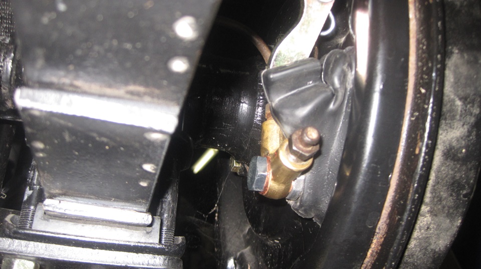
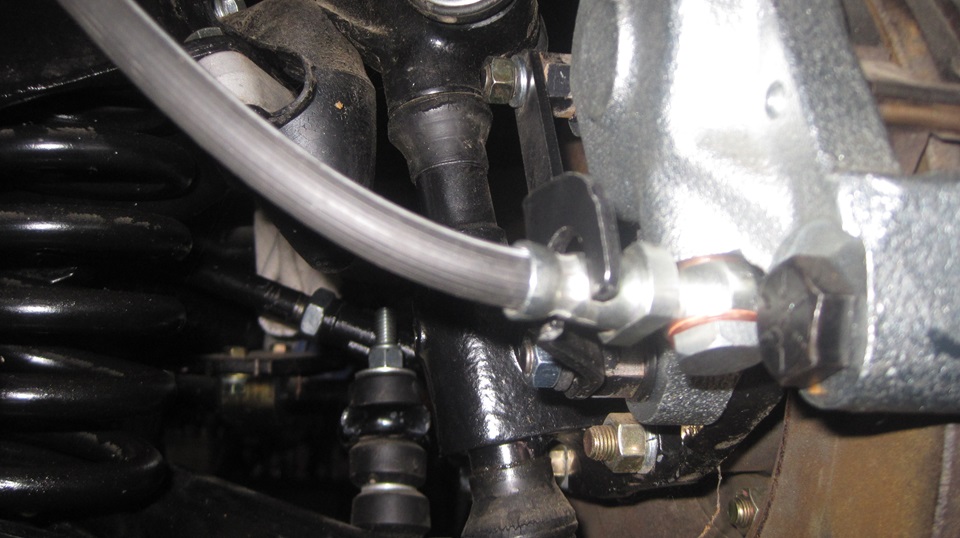
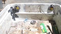
 Looks like we have all the parts needed to finish the brakes on the rolling chassis. Start with installing the right front hose banjo bolt with seal washers, and the right rear pipe banjo bolt with seal washers. That finishes sealing up the hydraulic system.
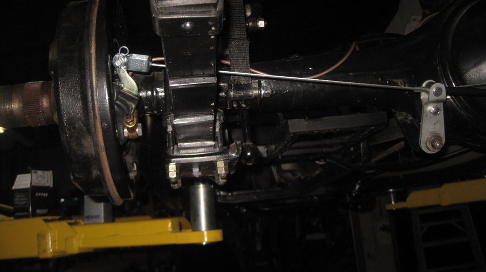
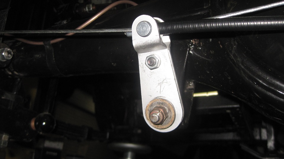
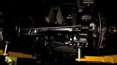
Then install the parking brake cable, beginning at the.equalizer lever assembly. We were missing an anti-rattle wave washer here, but lucked out where Stu had saved the one from prior assembly (bit of a miracle). With the cable jacket running through the equalizer trunnion, connect the clevis with pin at the LR and RR slave levers. the cables pass very close behind the axle banjo housing, may touch, but not always.
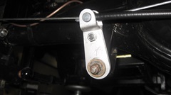
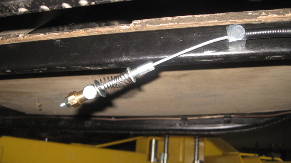
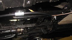
The cable outer jacket goes below the axle housing, then passing forward through a special elongated floating P-clip. It is then secured to the bottom of the right side battery carrier tray with a standard P-clip along with he brake pipe and a spacer on the screw (six flat washers make a good substitute spacer here). Front end of the cable terminates at a fixed trunnion on the frame just inside the right side of the tunnel. Proper fittings at the adjustment end of the cable are a standard flat washer, a compression spring, large OD flat washer, a floating trunnion, the adjusting brass saddle nut, and a jam nut. In service the floating trunnion rides in bottom end of the hand lever shaft output lever, while the large washer sits against the back of the lever.
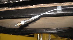
The lever is not there yet, because it attaches to the tunnel, which has not been installed yet.Then we were updating inventory count and adding the consumed parts to the wish list for future re-order for re-stocking the Magic Trailer. There was a Bluegrass and Rock concert in the park tonight, but I missed it while I was processing these photos and notes.
Sunday August 25, 2024
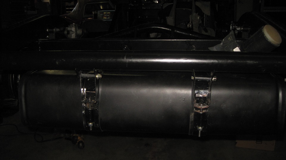
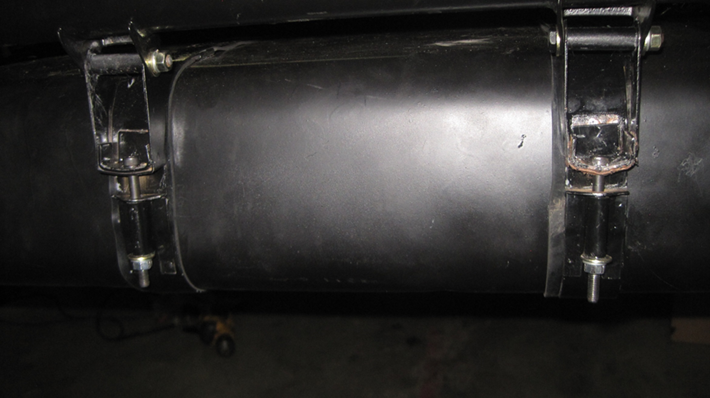
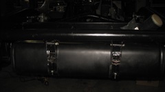
Been chilly for a few days, but nicer working weather today, so we got an earlier start. Time to install the fuel tank in the rolling chassis. Took a while to find enough fasteners, then on with the show. The rubber packing straps from Moss Motors were too wide, so we clipped notches in the edges to fit within the side guides on the tank. While cutting, I noticed the rubber was bad enough that I could tear it with my fingers, so this is another crap rubber part from Moss. But being trapped by the mounting straps it will likely be okay in service, at least until the next time it needs to be disassembled. I think the rubber must also be thicker than original issue, because we had hard time connecting the strap ends, needing to use longer bolts. And when finished, the strap ends didn't come all the way together, more like metal to metal ends butting up rather than overlapping. Persistence pays, and it was eventually installed.


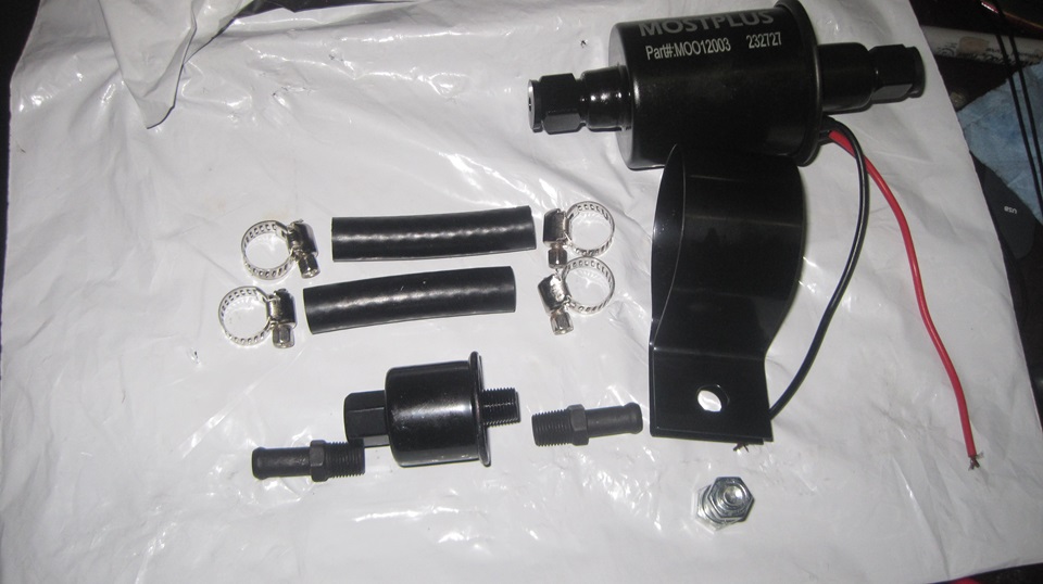
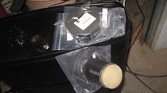
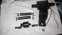
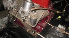
Attach the new tank-to-pump fuel pipe to the tank, and pull out a new universal electric fuel pump. In addition to the parts shown, we also use two 1/8-NPT street ells to make 90-degree turns at both ends of the pump, so the pump can stand on end with outlet end up as specified.
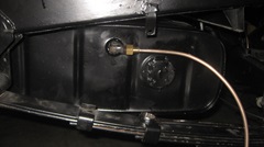
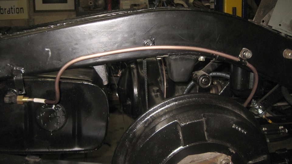
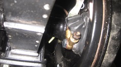
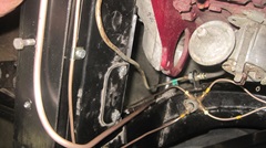
Route the fuel pipe from tank to pump on the outboard side of the frame above the rear axle out of harm's way. There is one large P-clip securing the pipe to one of the bolts attaching the shock absorber to the frame. The pipe was originally connected to the SU fuel pump with a flare nut fitting, but is now connected with rubber hose and hose clamps. The sending unit was originally grounded through the tank and steel pipe and fuel pump (which had its own grounding wire). This hose coupling will now require addition of a grounding wire from the fuel level sending unit to the chassis frame.

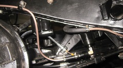
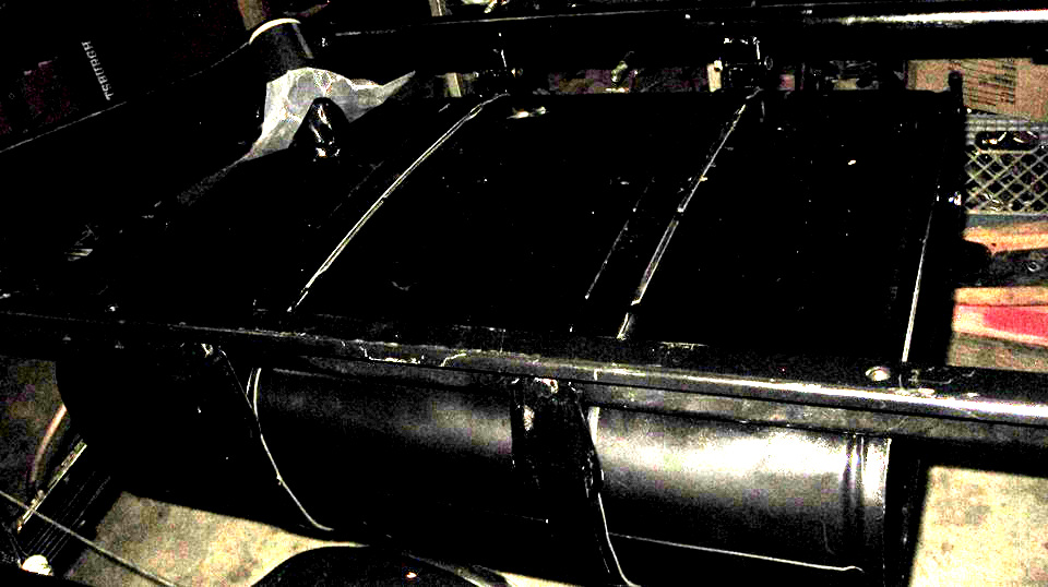
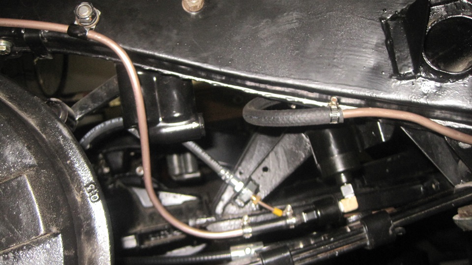
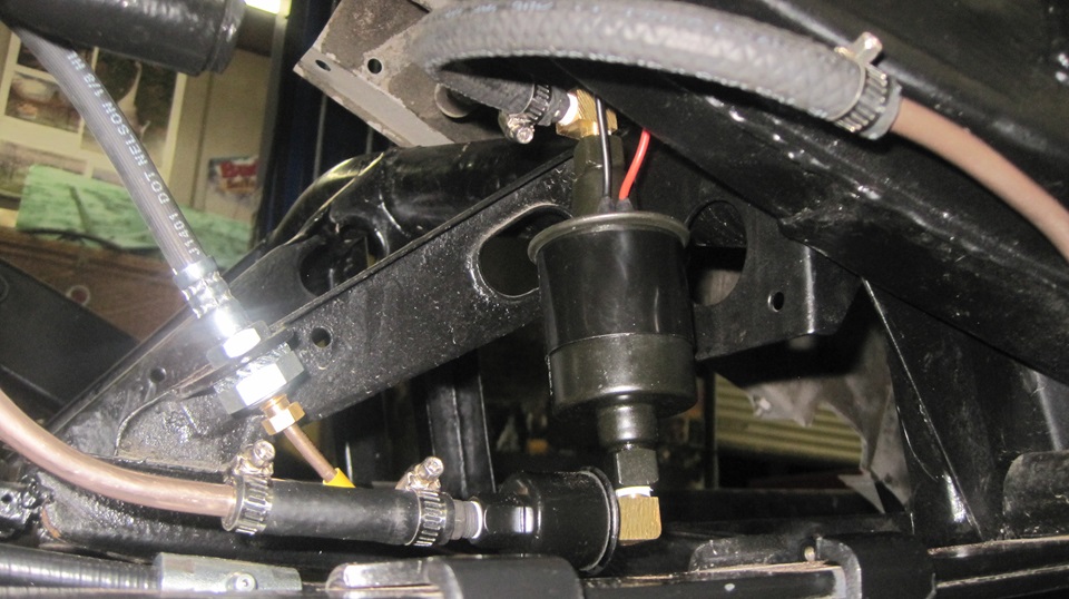
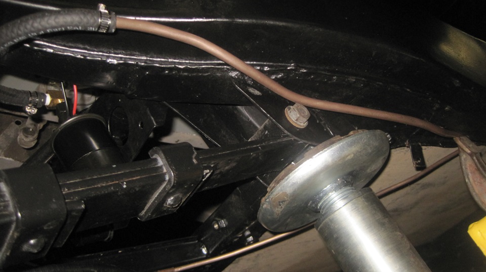
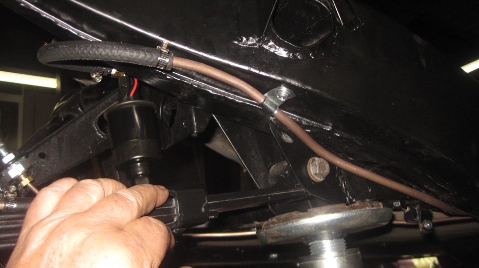
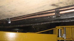
At the top outlet end of the pump another street ell is pointing rearward with a hose barb. Here the hose does a 180 degree turn to connect to the fuel pipe going forward below the frame. Where the hose connects to the pipe with a hose clamp, we still need to install a P-clip on the pipe, drill and tap bottom of the frame to accept the mounting screw. Next picture is a top down view of the fuel pump installed. Third picture shows the pipe routing below the frame, against the leaf spring bracket, above the bolt for the leaf spring, then continuing forward below the frame. Notice how the pipe avoids the lifting point for the hoist. Please disregard the temporary C-clamp on the far right.

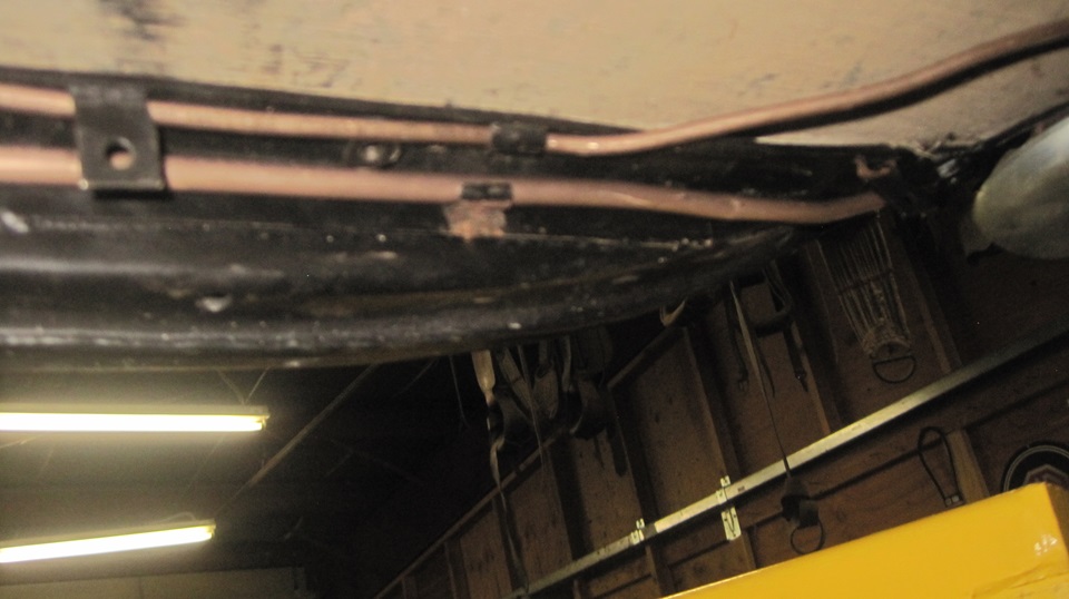
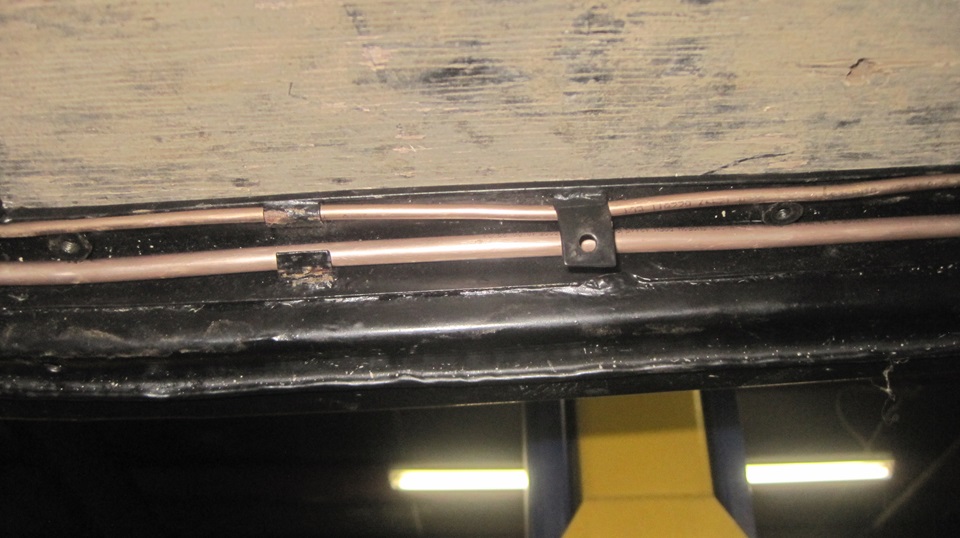
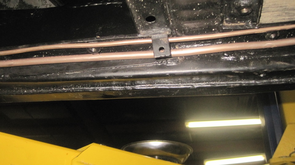
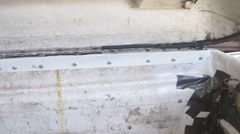
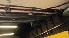
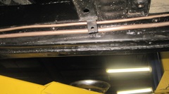
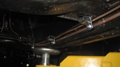
Here is a picture series showing the fuel pipe running under the right side frame from back to front along with the brake pipe. First picture below from right to left shows the rear crimp tabs, followed by a weld nut for a floor board bolt (between the pipes), followed by the rear most hanging tab for securing the wiring harness (later). The pipes need to be nicely tucked into the corners to avoid the floorboard bolts. Picture center below shows the same rear hanging tab followed by the second or center crimp tabs for the pipes, followed by another weld nut between the pipes. Third picture, proceeding forward below the frame cross member, shows the second or center hanging bracket for the harness, followed by another floorboard weld nut.

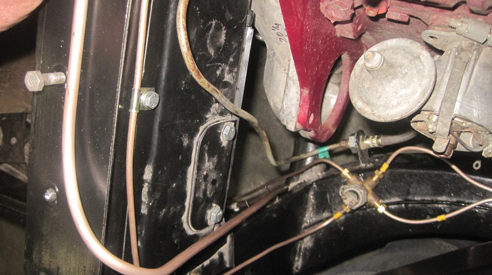
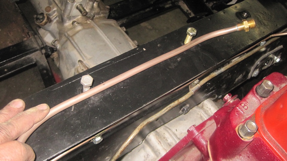
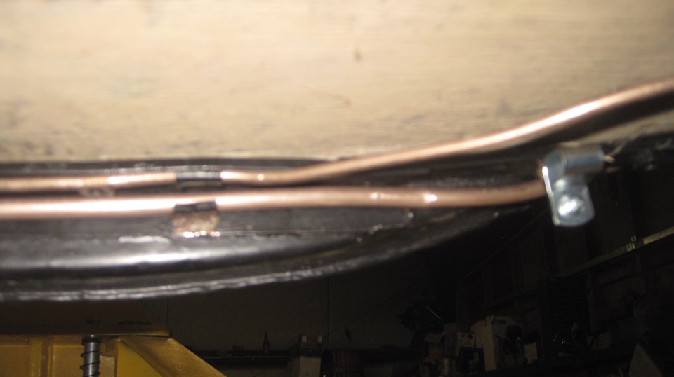
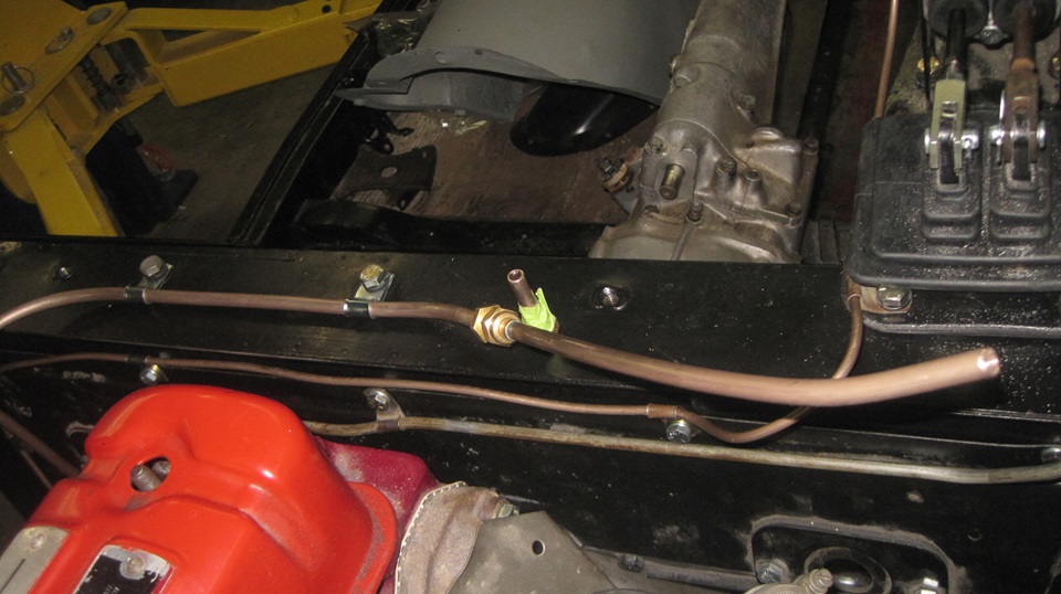
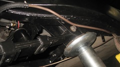
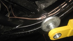
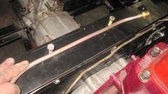
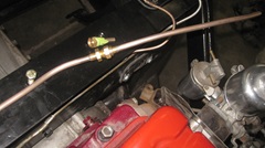
Continuing forward we have the forward hoist contact point under the frame. Here you can see the forward crimp tabs for the pipes, followed by another floorboard bolt weld nut, and the forward hanging bracket for the wiring harness. From here the pipes proceed forward and upward along the inboard surface of the right leg of the frame goal post (outboard of the clutch hydraulic pipe). The center picture below shows the fuel pipe in lower left corner of the picture rising past the frame closure plate, curving around in front of the goalpost to go on top of the goalpost. The third picture shows where the fuel pipe runs on top of the goalpost, eventually to be on top of the heater shelf once the body is is installed. Here the fuel pipe will be secured with two p-clips (not yet installed) on the two bolts that are present. Notice the output end of the pipe with male threaded fitting turned slightly upward and forward for connection of the fuel flex pipe for the rear carburetor as original for the MGA.
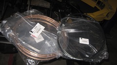
 The last two pictures at right show the off-cut flare nut pipe ends left over after connecting the two fuel pipes to the aftermarket electronic fuel pump with hoses. One short pipe and one longer pipe which can be used as needed to connect the MGA fuel supply pipe to the MGB carburetors with additional flex hose.
 Been a long day, got late, call it a night,and finish these photos and notes tomorrow. Been a long day, got late, call it a night,and finish these photos and notes tomorrow.
Monday- August 26, 2024
Needing a break, we did breakfast at McD in Angels Camp, catching up email and bbs. Finished posting the photos and notes from yesterday. Made some calls, then ran to the hardware store and to O'Reilly AP looking for P-clips, but not much luck. Quick pass by a grocery store on the way back up the hill.
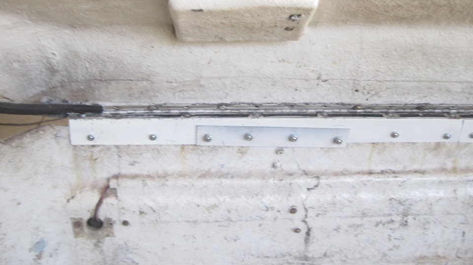
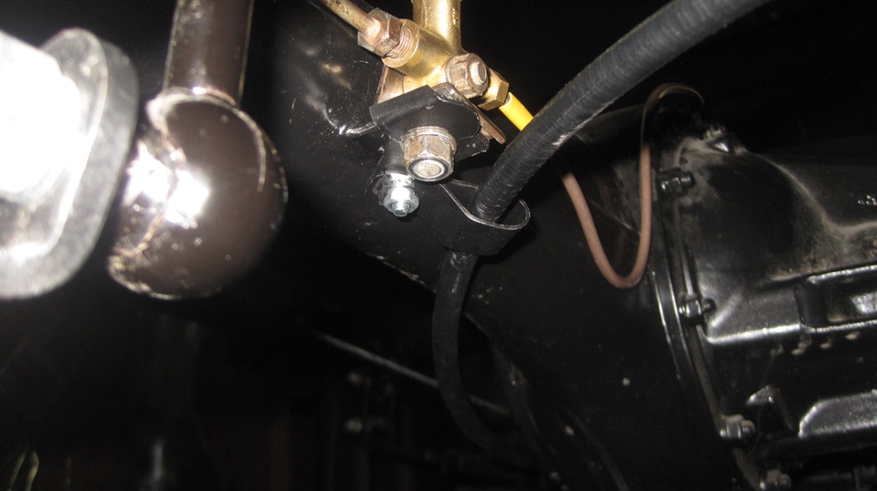
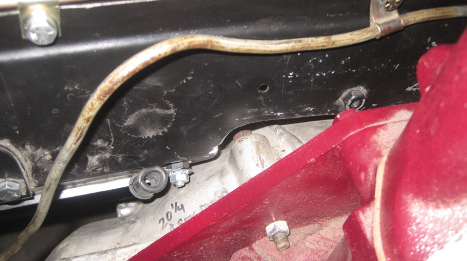
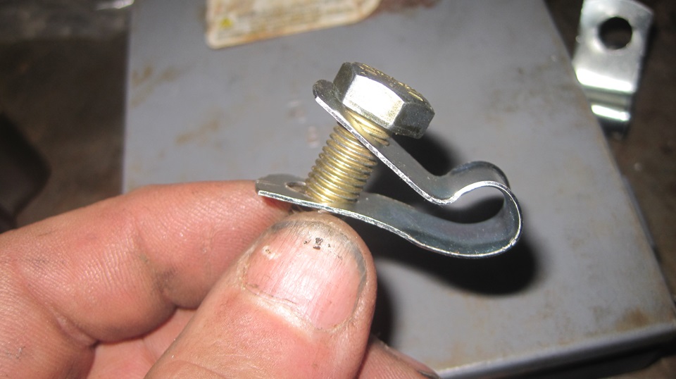
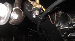
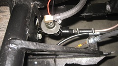
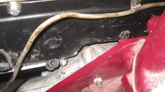
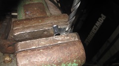
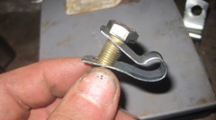
 We did find one more P-clip of significance.It was a Moss part number with a slight dimensional error. Supposed to be 5/16" loop size and 7/32" hole for a #10 screw. The hole was clearly oversize at a clean 1/4 inch, but close enough to serve the purpose here. I drilled a hole and tapped it for #10-32-UNF thread, and installed the P-clip to secure the rear end of the main fuel pipe under the frame near the fuel pump. Nice. -- I had in hand just two of the six required tandem P-clips for holding the main battery cable and wiring harness under the floor at the right side of the chassis. At least I could bolt those two parts on in the right places. The picture below right shows one more P-clip with a rubber grommet attached at top of the tunnel opening near top of the gearbox bellhousing. This one is to secure the speedometer drive cable en route to the heater shelf area.

Tuesday- August 27, 2024
I had in mind to place a parts order with Moss by early afternoon, but wishful thinking does not accomplish much. The Moss catalog and web site diagrams illustrate most of the required P-clips in the right places, but very few of them show part numbers,so cannot be ordered. Seems like Moss does not allocate enough manpower to post such details, cannot be bothered with sales of cheap small parts, even though they are not that cheap in quantity. There must be close to 40 part numbers and 100 pieces of such clips in the MGA, and similar for other vintage British cars I suppose. They must be missing a lot of sales.
I spent the entire day until late night chasing part numbers. I looked up the original BMC numbers in the Service Parts List, then went searching on line with those numbers. I also spent lots of time rummaging through various vendors web sites looking for the P-clips, but still not much luck. Worse than pulling teeth, I don't know how people ever manage to restore these cars. In the end I had only half a dozen part numbers from Moss, and about 20 more BMC numbers with no source. Way past midnight and running out of time (days), so I hope I can do better tomorrow.
Wednesday- August 28, 2024
A bit short of sleep, but back on the run by mid morning. Thought I had as many Moss part numbers as I could get, so going to call in the order about noon. After ordering the Moss part numbers I knew, I began to ask about the BMC part numbers, and fortunately the sales rep was being cooperative. For the P-clips, all of the BMC numbers begin with"PCR", which I presume stands for P-Clip Rolled edges". This is followed by four numeric digits indicating the barrel bore and bolt hole sizes. For example, PPCR0509 has 5/16" bore and 9/32" screw hole (for a 1/4" bolt). The sales rep was soon looking up any Moss numbered P-clips he could find, and checking the dimensions. I was wondering if the Moss data base could look up BMC part numbers (which it can't). But then we tried searching for "PCR", and it came up with 22 Moss numbers for P-clips. So there must be some BMC number information somewhere in the data base.
Perhaps half of those listings had the two dimensions for the P-clip, so I could run through those first to see if any of them were on my wanted list, and several were. So Moss did have some of these parts in stock, just not publicly listed. So I put the order on hold and spent the next two hours checking the spec's on all 22 of the search findings. I did pretty good with18 Moss part numbers on the order, and 8 BMC numbers not yet solved. The order was finished by 2:30pm-PDST, so hopefully it can be picked, packed and shipped today. Just over $10
0 for P-clips including shipping, but such is life, we need the parts.
Thursday- August 29, 2024
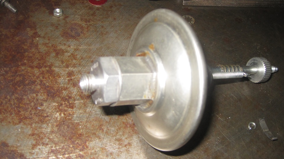
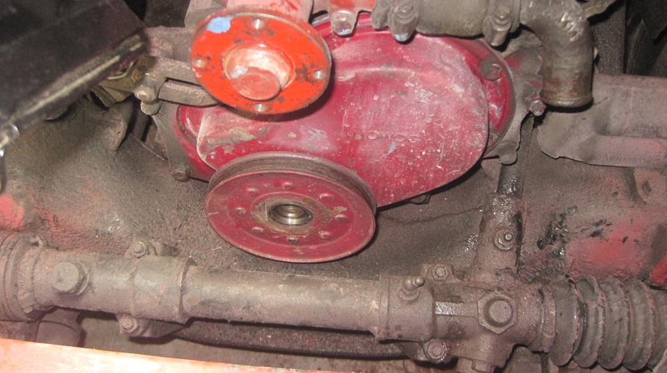
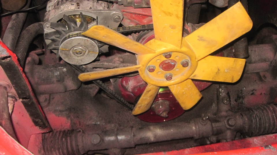
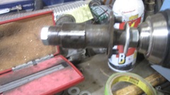
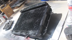
We have a few things to do for our own MGA today. Start with removing the radiator and fan pulley that has been chewing on our fan belts for the past two months. Install the new pulley., reinstall the fan,and re-tension the fan belt.
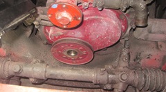
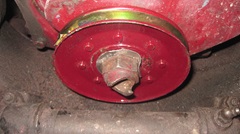

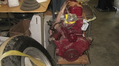
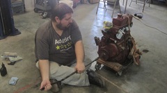
Then we put the slightly irregular pulley back on the spare engine where we borrowed it from back in mid June (just before the deer strike). While we have our hands on it, roll the spare engine out, remove the spark plugs, put a touch of oil in the cylinders, give it 50 turns with the hand crank to circulate some oil, and put the plugs back in. Best we can do to get it oiled up inside after sitting for two years.
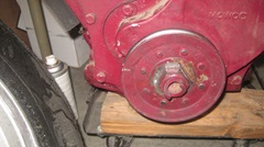
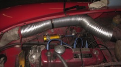
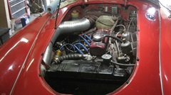
Quick paint the radiator before reinstalling it, and set it out in the hot sun to dry. That covers up some red overspray from when we were hastily repairing deer strike damage in late June. -- Then something I've been wanting to do for about 20 years. You know that pesky paper and foil 4-inch air duct that gets smashed every time you put your hands in the engine bay to fiddle with the distributor? We recently bought a flexible aluminum corrugated 4-inch clothes dryer vent tube. So rip out the smashed paper tube and install the nice metal duct (very easy). For the middle 1/3 of the length we spiral wrapped it with two layers of Duck Tape for electrical isolation were it passes close to the starter switch. This is to prevent shorting the battery cables to ground on the metal duct when using jumper cables. With that finished, put the radiator back in,fill with coolant, and it's good to go.
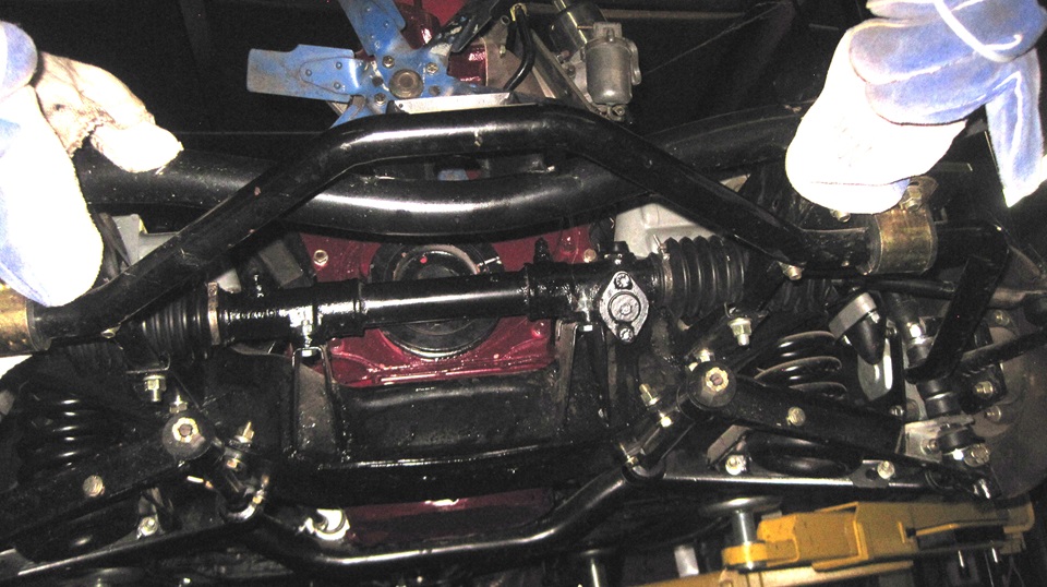
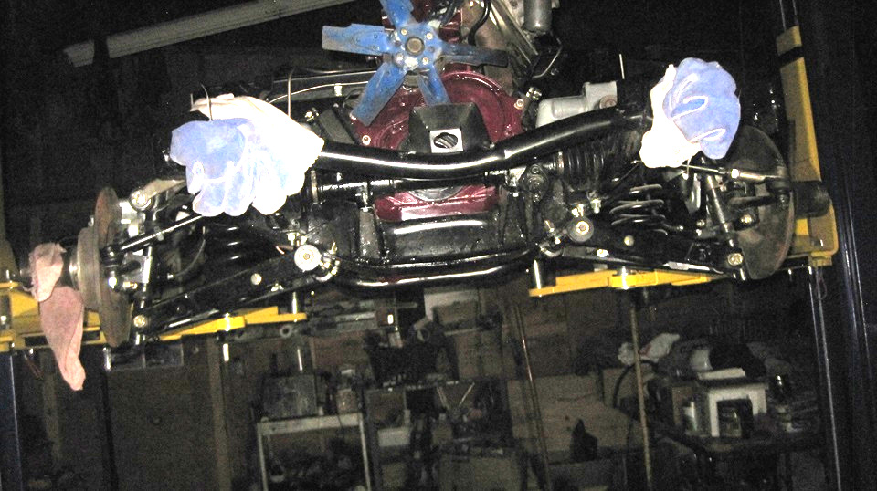
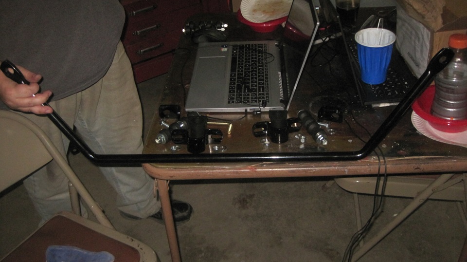
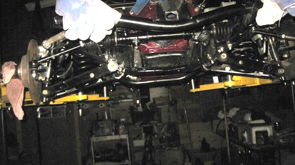
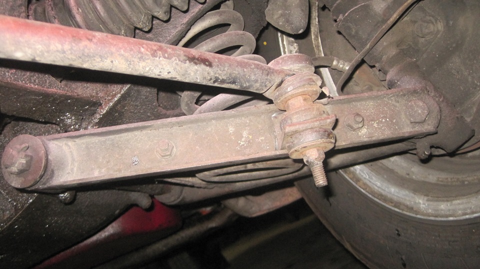
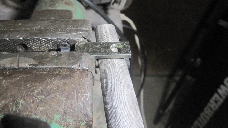
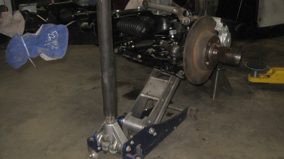
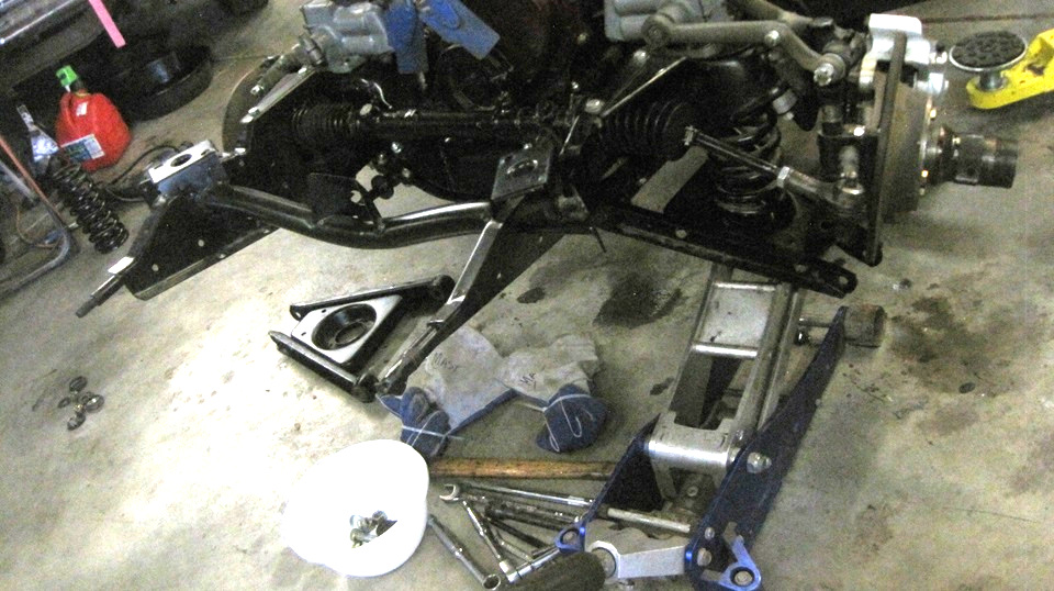
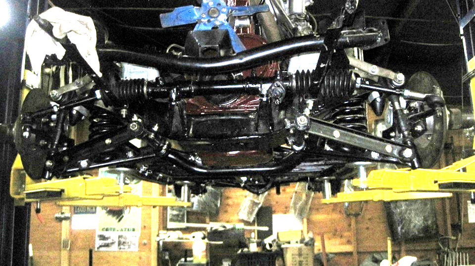
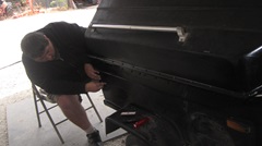
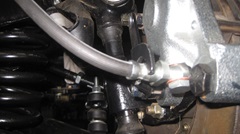
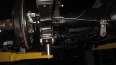
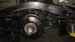
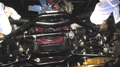
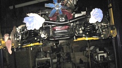
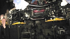
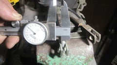
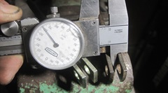
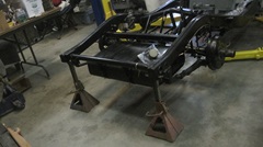
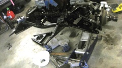
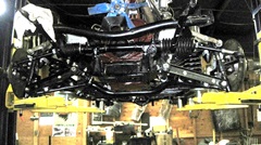
For the next challenge we will be replacing the front anti-sway bar on the restomod rolling chassis. Apparently someone supplied the wrong part, and Stuart made special brackets to install it. The big problem is, the bar is 1-inch diameter.Stiffness of a torsion bar increases as the 4th power of the diameter). ,That makes it 3X stiffer than the desired 3/4-inch bar, so it has to go. The 1-inch bar is shown installed in the first picture, removed in the second picture. The new aftermarket Addco 3/4-inch sway bar kit is in the third picture. This was supposed to be easy, just drill six holes and bolt it on, but there was a problem.

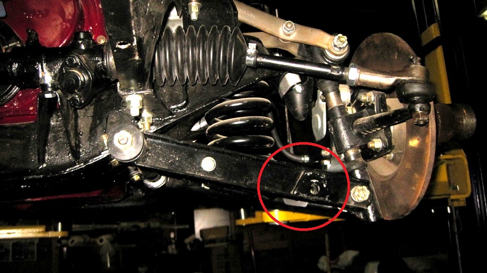
Distance between link holes in the lower suspension arms is 35 inches, a consequence of front A-arm brackets from late production MGA, after the factory made a front sway bar an optional accessory. Apparently the Addco bar was designed and produced before the factory option. While it was designed to work well (and easier to install), it does not fit the same as the later factory option bar. Distance between the end links for the Addco bar is 32-1/2 inches. So the problem is, there is a trapezoidal plate welded into the later style front A-arm bracket, and that piece is obstructing installation of the Addco link bracket. Bummer. After much measuring of both the rolling chassis and my MGA 1500 car, it turns out all we have to do is move the late style front bracket from front to rear, and move and the early style rear bracket to front. Simple,except we need to compress the coil spring to remove the lower trunnion bolt before we can lower the A-arm for disassembly. That's easy with a fully assembled car, just jacking under the A-arm. Not so easy with less weight of the rolling chassis without the body on it. Job for tomorrow.


Friday- August 30, 2024
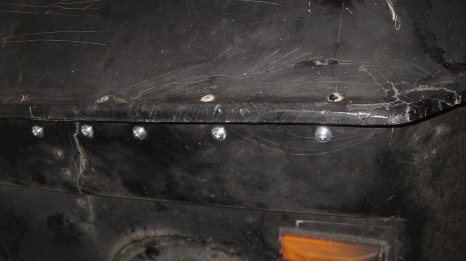
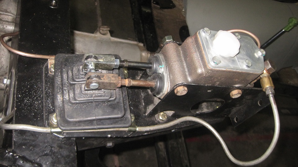
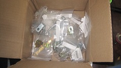
Mail call. The Moss parts ordered Wednesday have Arrived. Some hand brake parts to put back in inventory, and lots of P-clips. Take time to update the inventory list before getting to work installing some of them. Start with four more tandem clips (total six) for battery cable and wiring harness under the frame. Back up top to install master cylinder pushrods, but the new clevis parts didn't fit. The inside slots measure exactly 1/4 inch when they need to be clearance slots at least 0.260" wide.
One original older part did indeed measure 0.265", so get out the hand file and have at it. Several minutes later we had two pushrods installed with one old and one new clevis. Okay, take the time to file out the other new clevis before we put it in inventory in the Magic Trailer. And we did get four P-clips installed either side of the pedal excluder for the clutch and brake pipes.


Bound and determined to install the last two P-clips for the fuel pipe on top of the goalpost. But we didn't have the clips, and haven't been able to find them for weeks. Moss doesn't even have a part number for it. But for the shipment just received, I did order a couple pieces of every P-clip we could find numbers for, even some MGB parts we may never use. Needing clips with 5/16 tube size and 11/32 bolt hole,we finally found two pieces 5/16 x 9/32. Close enough for a G-job, so we drilled out the attachment holes to 11/32, and we were back in business. Didn't get to the front suspension mods yet, maybe tomorrow.

Saturday- August 31, 2024
I had to call Basil Adams this morning to report the weak nylon rebound strap, and see if he could talk to Strapping Lad about making them with wider and thicker webbing material or making multiple layers to have stronger finished parts that wouldn't cold creep and stretch with time under load. That didn't go well. One of the less pleasant things I have to do when a vendor may take offense at the suggestion that anything they sell might be less than perfect. That negotiation may require more time and patience.
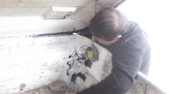
We ran out of drinks and low on food, so there was a morning trip for a food run. Then we finally got serious about rearranging front suspension parts on the rolling chassis to allow the aftermarket Addco sway bar to be installed. The idea was to move the front A-arm bracket to the back, so the welded trapezoid plate would not be in the way. the bracket cannot be inverted, because the large bolt hole is not on the center line. Solution is to also move the offending bracket from left to right side. The simpler explanation is, just move the three-piece A-arm assembly to the other side, exchange left and right side parts.
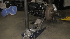
With no body weight on the chassis, we need a little finesse. Set two jack stands under the far rear corners of the frame to have the chassis mass as far forward as possible. Place two more stands far enough forward to prevent the chassis from tilting forward. Place a floor jack directly under the coil spring, and raise the suspension until the shock arm lifts off of the rubber bumper to unload all suspension parts except the A-arm inboard pivots. This is when you can replace the shock absorber, if that was needed (but not today). -- Remove the lower trunnion bolt,and lower the floor jack until the coil spring falls out. Then disassemble the A-arm enough to remove it from the inboard pivots.
We also had to install a 1/2-inch bolt each side to fill the hole where the factory sway bar link was intended to fit, because it holds the late style spring pan assermblies together. We do the same for the other side of the car, then swap the A-arms from left to
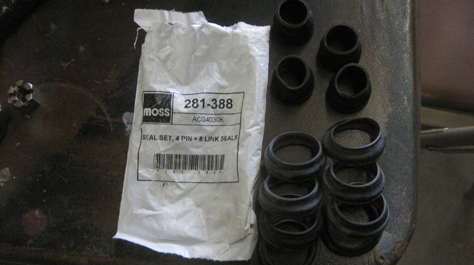
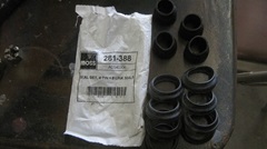 right, and put it back together. In the process we found the two year old rubber trunnion seals to be rotted and falling apart, so pull a new set out of the trailer. Reassembly is the reverse of disassembly. Always fun reassembling the trunnion seals and bolts with the compression load on the coil spring on top of the floor jack. We were lucky on weight distribution, only had to set navigator on the front corner of the frame to get the last trunnion bolt installed. -- Concert in the park again tonight, so it was a good time to knock off the noise around 6-pm and get after posting the photos and notes
|